VALAWAI Architecture
The VALAWAI value awareness architecture comprises three layers: C0, C1, and C2.
The C0 layer consists of components responsible for information extraction and task execution. They process data from the environment and transmit this information to the C1 components. Their specific tasks depend on the application, but examples include components for face recognition, sentiment analysis, topic modeling, and emotion recognition. Many of these modules are available on the AI on Demand (AIoD) platform (the successor to the AI4EU platform), and VALAWAI focuses on integrating existing modules into the architecture, developing new C0 components only when necessary.
The C1 layer contains components that integrate and analyze information from the C0 components and make decisions accordingly. Unlike C0 components, readily reusable C1 components are expected to be less common, as their functionality is highly dependent on the specific use case.
The C2 layer is the reflective layer, analyzing the value alignment of behavior.
These components are a key innovation of VALAWAI, and they are where value-based
reasoning takes place. This requires capabilities such as value acquisition, value
representation and reasoning, value alignment mechanisms, and value-driven
explainability. These components can influence behavior in two ways:
- Directly modifying a system's behavior:
- Modifying the internal behavior of C0 and C1 components.
- Modifying the connections (topology) between C0 and C1 components.
- Indirectly modifying a system's behavior: Providing value awareness feedback to C1 components, with the understanding that increased value awareness influences behavior.
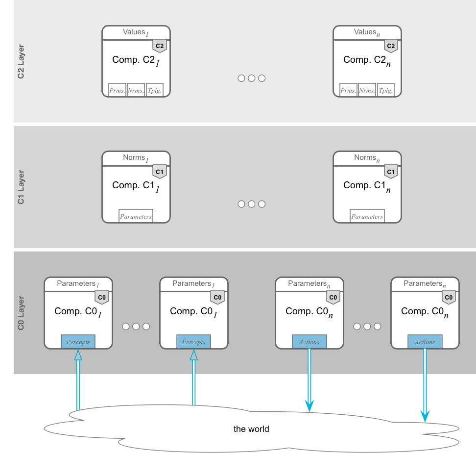
This section describes the VALAWAI architecture by modeling the components of each layer and their communication channels. To improve readability and clarity, given the complexity of the communication channels, we present each type of communication separately.
We distinguish between data flow (single-line arrows) and control flow (double-line arrows). Data flow represents information exchange between components (e.g., a C0 component informing a C1 component about detected hate speech). Control flow enables control over other entities (e.g., a C1 component updating the parameters of a C0 component's adapter module to refine hate speech detection). Control can be exerted not only over system components but also over the system's topology. For example, a C2 component might decide to switch a C1 component's connection from one C0 hate speech detector to another that incorporates user feedback. Control can also extend to the real world (e.g., a C0 component suspending a user from a community).
For a component to exert control, it needs a representation of the controlled entity. For example, a C1 component needs knowledge of a C0 component's parameters to update its adapter module. This might involve the C0 component sharing its representation with C1. Similarly, a C2 component needs to understand the topology to modify it. Therefore, most control flow is represented by bidirectional arrows, even if control is unidirectional.
We present the VALAWAI architecture by separating data flow and control flow, and further differentiating the types of control flow. The architecture (see Figures below) illustrates that each layer (C0, C1, C2) can have multiple components. Unlike the GNW, we posit that complex processing systems are not required at the C0 layer, delegating this task to the C1 layer. C0 components can thus be sensors or actuators. More complex behavior can be constructed by connecting C0 components through data flow channels.
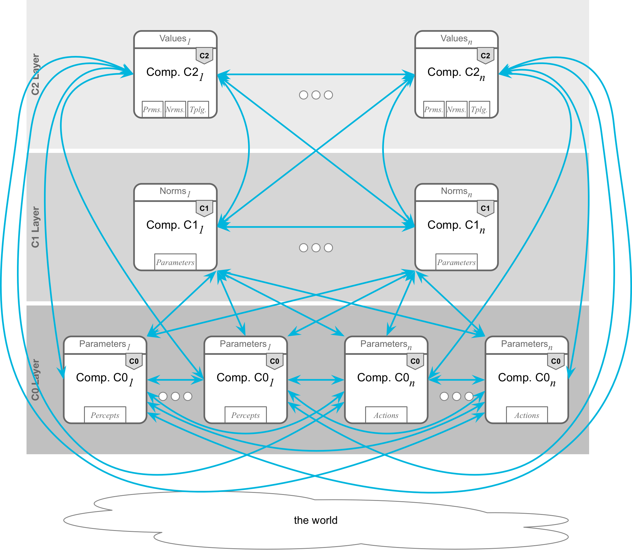
Data Flow
Components can communicate with other components within the same layer and with components in other layers. For example, C2 components can communicate among themselves (sharing reflections), with C1 components (providing value alignment feedback), and with C0 components (receiving value-related information). C1 components can communicate among themselves (collaborating on decisions) and with C0 components (receiving extracted features or sending action instructions). C0 components can also communicate among themselves (agreeing on which features to share with C1).
Inter-layer communication facilitates self-organization and attention focusing, especially at the C1 and C2 layers. Whether this is centralized or distributed is an implementation detail to be addressed later.
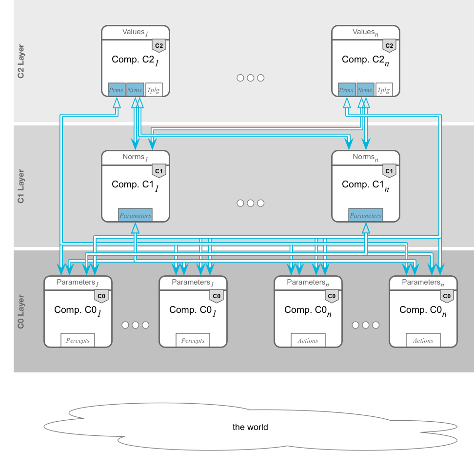
Control Flow: Control over System Components
C1 components, responsible for decision-making, can control C0 components, tuning their behavior. C2 components, reflecting on values and value alignment, can also adjust the functionality of both C1 and C0 components to ensure value alignment. We currently assume that components within the same layer do not control each other, as self-organization and attention focusing can be achieved through data flow.
Control flows downwards: C2 controls C1 and C0, and C1 controls C0. How are C2 components controlled? Since C2 components reason about human values, their behavior is guided by those values. Control over C2 components is thus achieved by controlling the relevant values. We currently assume manual, offline selection/specification of preferred value systems, but future work may explore direct user influence on the relevant value system.
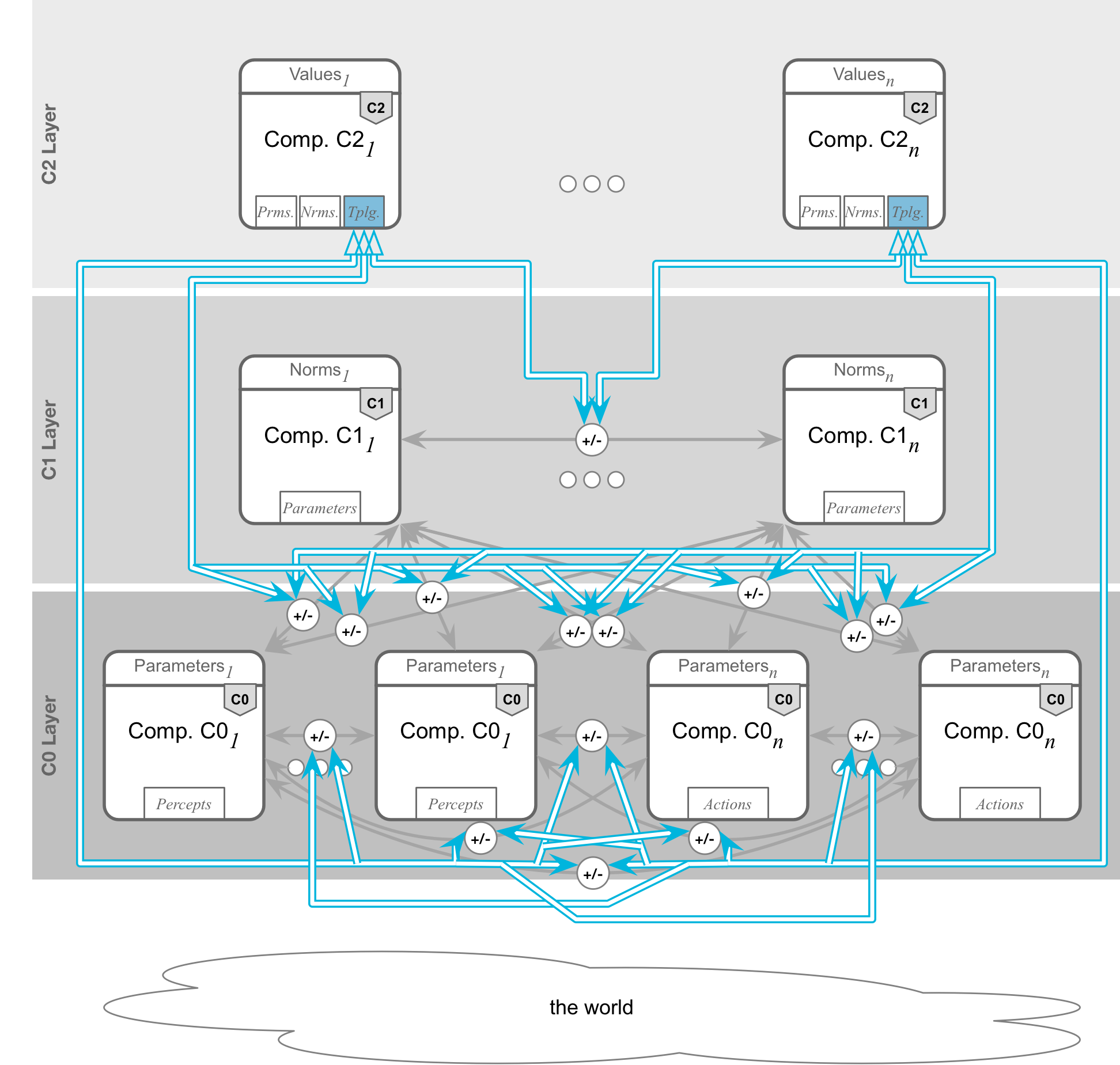
Control Flow: Control over the Topology
C2 components can also control the behavior of C1 and C0 components by controlling the connections (topology) between them, activating or inhibiting data communication. Data flow to/from C2 components, however, should remain unaffected, as communication with value-reflecting components should be open.
Control Flow: Control over the World
Control over the real world is exercised through C0 components: sensors observe the world and transmit observations to C1, and actuators perform actions in the world. C2 and C1 components can only impact the world through C0.
Component Architecture
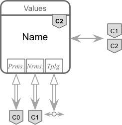
The image below shows the generic architecture of a system component. Component types depend
on their layer (Cᵢ ∈ {C0, C1, C2}). Each component has parameters that define its behavior.
Interaction with the environment occurs both within and outside the system.
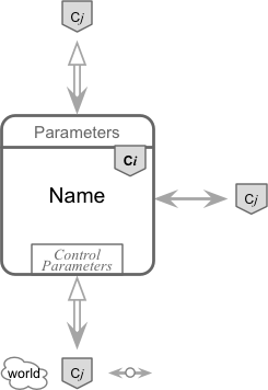
Environmental interaction falls into two categories: communication with other components (data flow) and control over the behavior of the environment (control flow).
Data flow is represented by single arrows and is only possible with other system components (Cⱼ).
Control flow is represented by double-lined arrows. Incoming arrows to a component's parameters represent control over its behavior (by modifying its parameters). Only system components can control other system components. The bidirectional nature of the double arrow indicates that the controlling component has a representation of the controlled component's parameters.
Outgoing double-lined arrows represent a component's control over other entities: other system components (Cⱼ), the system's topology (data flow arrow), and the external environment (cloud). Control is exercised through control parameters. The bidirectional arrow again signifies awareness of the controlled entity and its parameters.
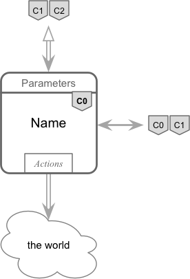
C0 Component
The C0 layer is the information extraction layer. C0 components interact with the physical world through sensors and actuators. Their behavior is defined by a set of parameters.

C0 components can be sensors or actuators. More advanced C0 components can interpret sensory information or actuation commands (e.g., sentiment detection, robot motion planning).
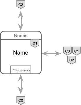
C1 Component
The C1 layer is the information integration layer. C1 components are decision-making components that process information from C0 components. Their behavior is governed by norms.
C2 Component
C2 components are responsible for reflection, which in VALAWAI is value-driven. Their behavior is determined by a set of values. The architecture is generic and could be applied to reflection driven by other factors.